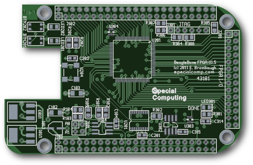
BeagleBone FPGA Expansion Board

BeagleBone FPGA PCB Rendering

Rendering of BeagleBone FPGA PCB

What is it?

This is a small (3.4" x 2.15" - standard BeagleBone "Cape" dimensions) board with a Xilinx Spartan 3A 200Kgate FPGA connected directly to the BeagleBone expansion connectors. Designed to stack with the BeagleBone according to the method described in the System Reference Manual, it provides the following features:

Background

Motivation

This board was conceived as a general-purpose I/O board with sufficient on-board logic resources to support experiments in digital audio, Software Defined Radio, robotics and general experimentation.

Design Details

Expansion Connectors

Although the BeagleBone Expansion Connectors provide interfaces to the GPMC, LCD/Video, McASP, SPI, I2C, UARTs, Timers, Interrupts, GPIO and ADC of the AM3xxx SOC, connecting to all of these is not possible with the FPGA used on this board so the BeagleBone FPGA board only connects to the GPMC bus, SPI0 and I2C2. Access to the other available interfaces is possible by stacking additional boards.

The GPMC expansion pins are available on connector P8 pins 3-26 and provide 24-bits of I/O which can be multiplexed for a variety of purposes as shown in the table below:

PinFunction
3GPMC_AD6/MMC1_DAT6//////GPIO1_6
4GPMC_AD7/MMC1_DAT7//////GPIO1_7
5GPMC_AD2/MMC1_DAT2//////GPIO1_2
6GPMC_AD3/MMC1_DAT3//////GPIO1_3
7GPMC_ADVN_ALE/TIMER4/GPIO2_2
8GPMC_OEN_REN/TIMER7/EMU4/GPIO2_3
9GPMC_BE0N_CLE/TIMER5/GPIO2_5
10GPMC_WEN/TIMER6/GPIO2_4
11GPMC_AD13/LCD_DATA18/MMC1_DAT5/MMC2_DAT1/EQEP2B_IN/PR1_MII0_TXD1/PR1_PRU0_PRU_R30_15/GPIO1_13
12GPMC_AD12/LCD_DATA19/MMC1_DAT4/MMC2_DAT0/EQEP2A_IN/PR1_MII0_TXD2/PR1_PRU0_PRU_R30_14/GPIO1_12
13GPMC_AD9/LCD_DATA22/MMC1_DAT1/MMC2_DAT5/EHRPWM2B/PR1_MII0_CRS//GPIO0_23
14GPMC_AD10/LCD_DATA21/MMC1_DAT2/MMC2_DAT6/EHRPWM2_TRIPZONE_INPUT/PR1_MII0_TXEN//GPIO0_26
15GPMC_AD15/LCD_DATA16/MMC1_DAT7/MMC2_DAT3/EQEP2_STROBE/PR1_ECAP0_ECAP_CAPIN_APWM_O/PR1_PRU0_PRU_R31_15/GPIO1_15
16GPMC_AD14/LCD_DATA17/MMC1_DAT6/MMC2_DAT2/EQEP2_INDEX/PR1_MII0_TXD0/PR1_PRU0_PRU_R31_14/GPIO1_14
17GPMC_AD11/LCD_DATA20/MMC1_DAT3/MMC2_DAT7/EHRPWM2_SYNCI_O/PR1_MII0_TXD3//GPIO0_27
18GPMC_CLK/LCD_MEM_CLK/GPMC_WAIT1/MMC2_CLK/PRT1_MII1_TXEN/MCASP0_FSR/GPIO2_1
19GPMC_AD8/LCD_DATA23/MMC1_DAT0/MMC2_DAT4/EHRPWM2A/PR1_MII_MT0_CLK//GPIO0_22
20GPMC_CSN2/GPMC_BE1N/MMC1_CMD/PR1_EDIO_DATA_IN7/PR1_EDIO_DATA_OUT7/PR1_PRU1_PRU_R30_13/PR1_PRU1_PRU_R31_13/GPIO1_31
21GPMC_CSN1/GPMC_CLK/MMC1_CLK/PRT1EDIO_DATA_IN6/PRT1_EDIO_DATA_OUT6/PR1_PRU1_PRU_R30_12/PR1_PRU1_PRU_R31_12/GPIO1_30
22GPMC_AD5/MMC1_DAT5//////GPIO1_5
23GPMC_AD4/MMC1_DAT4//////GPIO1_4
24GPMC_AD1/MMC1_DAT1//////GPIO1_1
25GPMC_AD0/MMC1_DAT0//////GPIO1_0
26GPMC_CSN0/GPIO1_29

Additional connections on connector P9 are listed below:

PinFunction
12GPMC_BE1N/GMII2_COL/GPMC_CSN6/MMC2_DAT3/GPMC_DIR/PR1_MII1_RXLINK/MCASP0_ACLKR/GPIO1_28
17SPI0_CS0/MMC2_SDWP/I2C1_SCL/EHRPWM0_SYNCI_O/PR1_UART0_TXD/PR1_EDIO_DATA_IN1/PR1_EDIO_DATA_OUT1/GPIO0_5
18SPI0_D1/MMC1_SDWP/I2C1_SDA/EHRPWM0_TRIPZONE_INPUT/PR1_UART0_RXD/PR1_EDIO_DATA_IN0/PR1_EDIO_DATA_OUT0/GPIO0_4
19UART1_RTSN/TIMER5/DCAN0_RX/I2C2_SCL/SPI1_CS1/PR1_UART0_RTS_N/PR1_EDC_LATCH1_IN/GPIO0_13
20UART1_CTSN/TIMER6/DCAN0_TX/I2C2_SDA/SPI1_CS0/PR1_UART0_CTS_N/PR1_EDC_LATCH0_IN/GPIO0_12
21SPI0_D0/UART2_TXD/I2C2_SCL/EHRPWM0B/PR1_UART0_RTS_N/PR1_EDIO_LATCH_IN/EMU3/GPIO0_3
22SPI0_SCLK/UART2_RXD/I2C2_SDA/EHRPWM0A/PR1_UART0_CTS_N/PR1_EDIO_SOF/EMU2/GPIO0_2
41EVENT_INTR1/TCLKIN/CLKOUT2/TIMER7/PR1PRU0_PRUR31_16/EMU3/GPIO0_20

As configured here, the BeagleBone FPGA board supports multiplexed 16-bit device access with three CS lines for a total address space of 384kB. Because GPMC wait requests are not provided the bus speed will have to be reduced to accomodate the slowest device access in a single cycle.

Configuration

At power up the FPGA is set to Configuration Mode [001] (Master SPI mode) and loads itself from the on-board SPI Flash memory. By toggling several bits in the I2C2 port expander chip at bus address 0x38 the FPGA may be set to Configuration Mode [111] (Slave Serial mode) which allows the BeagleBone processor to load it via SPI0 at any time. Serial configuration is quite fast (less than 1 second) in either case and LED301 on the board will light to indicate a successful configuration.

Altering the content of the on-board SPI flash also uses SPI0. A special temporary 'pass-thru' FPGA design is required which provides a direct connection between SPI0 and the SPI Flash memory to support programming and verifying the contents of the flash chip.

A bitstream download application which uses kernel I2C and SPIDEV drivers to manage the process of configuration and programming will be provided for userland setup. Additionally, a simple C language library of support functions will be available that allows custom applications to take control of the FPGA board.

JTAG

A 6-pin JTAG header is provided for external configuration and debug. It conforms to the Digilent JTAG pinout, but can also be used with Xilinx download cables if flywires are used. This is handy for testing the FPGA without the Beagle attached, or for debugging designs using Xilinx's Chipscope application.

ID

A 32kbyte I2C EEPROM is available for conformance with the ID protocol described in the BeagleBone System Reference Manual. Two address select bits are provided with jumper settings to control the configuration order for stacked boards.

Port Expander

An I2C Port Expander chip is used to control the FPGA configuration process. It resides at I2C2 Bus Address 0x38. Be sure that there are no other I2C devices in the board stack that will conflict with this addresss.

I/O Header

The 28-pin I/O header on the right-hand side of the board connects directly to the pins of the FPGA, providing a completely configurable interface. 24 pins of I/O are provided, alongh with 3.3V power and ground.

FPGA

The Xilinx XC3S200A Spartan 3A FPGA on this board is inexpensive and provides sufficient I/O and logic resources to perform a wide range of interfacing and processing tasks. Simple signal processing, sequencing and control are certainly possible, as well as some buffering and reformatting using on-chip RAM.

LEDs

There are three LEDs are on-board:

Buttons

There are two user-defined buttons connected to the FPGA which allow real-time human control of FPGA functions. The buttons are physically aligned with LED201 and LED202 at the top right corner of the board.

Clocks

The BeagleBone expansion headers provide one clock from the AM3xxx SOC which is routed to the FPGA. This board also provides a crystal oscillator to generate a stable 50MHz clock suitable for high-accuracy timing.

Power

On-board 3.3V and 1.2V LDO regulators derive all the supplies required from the BeagleBone SYS_5V supply provided on the expansion connector. While the 3.3V and 1.2V regulators which supply the FPGA I/O and Core voltages are rated for close to 1A, it is recommended that FPGA designs which require high power are not considered for this board. Although the Spartan 3A chip used here can operate at fairly high internal frequencies approaching 200MHz, the practical limitations of power supply and heat management will constrain the designs that can safely be realized on this board.

Software

Kernel

Minimal kernel driver support required for the BeagleBone FPGA board includes I2C2 and SPI0 with SPIDEV, as well as pin muxing to make these interfaces available on the expansion port. Since the board conforms to the BeagleBone IDPROM standard it will be recognized by the bootloader.

User

A Beagle user-space application and access library will be provided which supports all the features on the board. The application can be used to download FPGA configuration files, program the SPI Flash memory, control the programmable clock oscillator and test the SPI control port. The access library provides a low-level API for control of the I2C and SPI ports, as well as higher level functions for bitstream download and may be used to construct complex user-space applications for interaction with the FPGA design.

FPGA Design

Synthesizing an FPGA design requires the Xilinx ISE Webpack which is a free download from the Xilinx website. This suite of tools includes a GUI IDE as well as command-line applications that can be run under both Linux and WinXX. Designs can be created with either Verilog or VHDL. Demo designs will be provided to showcase the capabilities of the board and will provide enough detail for starting on custom designs.

Design Documentation

Status

Return to BeagleBone page.

Last Updated
:2011-11-19

Valid HTML 4.01 Transitional